
CAN Bus Integration for Fleet Tablets: A Practical System Integrator’s Guide
Introduction
When system integrators begin planning CAN Bus integration for fleet tablets, the project often appears straightforward on the surface. Connect two wires, configure the baud rate, start reading vehicle data. The reality, however, is more complex. Deploying CAN Bus across a mixed fleet of trucks, buses, and heavy equipment—each with different electrical systems, different CAN architectures, and different data rate requirements—transforms the integration layer into the most challenging part of the project.
Most CAN Bus integration failures are not caused by protocol problems. They result from inadequate planning around the electrical environment, vehicle CAN network topology, and data bandwidth constraints that nobody calculated before installation begins. Understanding six key technical areas before wiring the first vehicle separates a smooth rollout from a costly support nightmare.
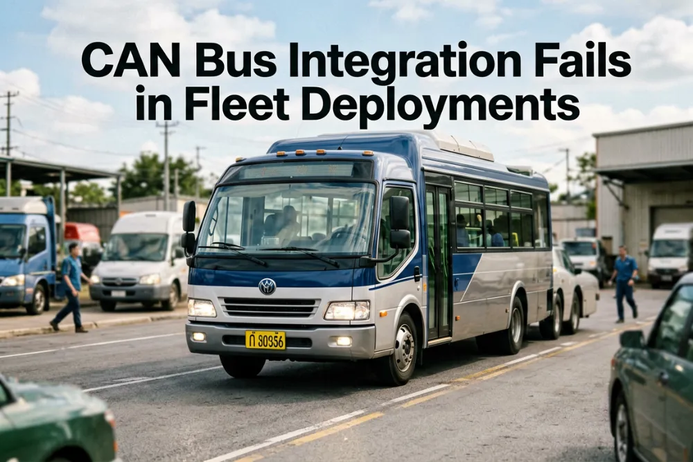
Why CAN Bus Integration Fails in Fleet Deployments
System integrators frequently report the same pattern: a CAN Bus configuration works perfectly during bench testing with a simulated ECU. The tablet reads data correctly, message IDs match, signal definitions are accurate. Then installation begins across 50 vehicles, and suddenly: intermittent data dropouts, missing engine hours, RPM values that freeze for 5 seconds then jump unexpectedly, and ELD log gaps that correlate with CAN bus errors nobody can reproduce in the workshop.
The root cause is rarely the CAN controller or the tablet hardware itself. It is the deployment planning—or lack of it. A real vehicle CAN bus operates in an environment fundamentally different from a bench test. The bench environment is electrically clean, isolated from other systems, and generates predictable traffic. A production vehicle generates electrical noise, experiences temperature extremes, encounters vibration, and carries traffic from dozens of other ECUs competing for bandwidth.
The specific challenge emerges when system integrators assume all vehicles of the same model share identical CAN architecture. In practice, different model years of the same truck can have different ECU gateways, different CAN message IDs, and different signal mappings. An integration that works perfectly on a 2023 Peterbilt 579 may fail completely on a 2020 model of the same truck—same manufacturer, same general design, but different electronic architecture.
Six Technical Areas That Require Planning
1. CAN Protocol Selection: J1939 vs CAN 2.0B vs CAN FD
Not all CAN networks use the same protocol. Selecting the wrong protocol layer means the tablet cannot interpret the data coming from the vehicle, even if the electrical connection is correct.
J1939 is a higher-layer protocol built on top of CAN, used in heavy-duty trucks, buses, construction equipment, and agricultural machinery. It uses 29-bit identifiers and operates at either 250 kbps or 500 kbps. J1939 defines standardized parameter groups for engine data, meaning the signal definitions are publicly documented—no OEM-specific files are required. However, the tablet’s CAN stack must implement the J1939 transport protocol to handle multi-frame messages correctly.
CAN 2.0B is used in light-duty vehicles, passenger cars, and some industrial equipment. It supports both 11-bit and 29-bit identifiers, but the message definitions are OEM-specific. Signal mapping varies by manufacturer, which means access to the vehicle’s DBC file (a database file containing signal definitions) is typically required. This access usually requires a relationship with the vehicle manufacturer or a third-party database provider.
CAN FD represents the next generation, supporting data rates up to 8 Mbps and larger payloads (64 bytes versus 8 bytes in classical CAN). CAN FD is not backward compatible with CAN 2.0B on the same bus, so the tablet’s CAN controller must explicitly support FD mode before it can be specified.
Before selecting hardware, document every vehicle make, model, and model year in the deployment fleet. This detailed inventory prevents costly rework after tablets are already installed.
2. Electrical Compatibility: Voltage Levels, Termination, and Grounding
CAN Bus is electrically robust by design—it uses differential signaling with error detection and fault confinement. However, these protections only work when the electrical installation is correct. Three issues cause the majority of fleet-wide CAN problems.
Termination resistors are the first issue. A CAN bus requires exactly two 120Ω termination resistors, one at each end of the bus. Adding a third device with its own termination resistor creates impedance mismatch and signal reflection. Removing both terminators causes the bus to float. Either condition produces intermittent errors that are extremely difficult to diagnose because they depend on bus load, temperature, and cable routing.
Ground offset between vehicle and tablet is the second issue. CAN differential signaling tolerates some ground offset, but if the tablet’s power ground and the vehicle’s CAN ground differ by more than a few volts, the common-mode voltage exceeds the transceiver’s operating range. This typically happens when the tablet is powered from a different circuit than the CAN interface. The solution is to use a common ground point for both power and CAN connections.
The third issue involves 24V vehicle systems. Heavy trucks, buses, and construction equipment use 24V electrical systems. However, CAN bus voltage levels remain the same regardless of vehicle voltage—CAN_H and CAN_L are referenced to the transceiver’s supply, not the vehicle’s battery. But the tablet’s power input must handle 24V. Tablets designed for fleet use support 9-36V DC input, covering both 12V and 24V systems without converters.
3. Dual CAN Architecture: When One Channel Isn’t Enough
A single CAN interface can read data from one bus—typically the vehicle’s powertrain CAN. Modern fleet applications increasingly need access to two separate CAN networks simultaneously.
One scenario involves powertrain CAN plus body CAN. The powertrain CAN carries engine data (RPM, fuel level, fault codes). The body CAN carries door status, lighting, HVAC controls, and driver controls. A telematics platform that monitors both engine health and driver behavior needs both buses simultaneously. Reading one bus, then the other, means missing events on the idle bus.
Another scenario involves vehicle CAN plus aftermarket sensor CAN. The tablet reads vehicle data from the OEM CAN bus while simultaneously communicating with aftermarket sensors—weight scales, temperature probes, tire pressure monitors—on a separate CAN network. This keeps aftermarket traffic off the vehicle’s mission-critical bus.
The key distinction is between dual independent CAN controllers versus a single controller with a multiplexer. Dual independent controllers allow different baud rates on each channel (for example, 500 kbps on J1939 powertrain, 250 kbps on body CAN) and simultaneous operation without channel switching latency.
4. Data Bandwidth Planning
A J1939 bus at 250 kbps can theoretically carry 1,500-2,000 messages per second. However, this represents the theoretical maximum of the transport layer, not a number to plan around. In practice, a heavily loaded vehicle CAN bus is already at 40-60% utilization before the tablet connects. The application must be selective about what it reads.
For ELD compliance, the mandatory parameters are EEC1 (engine speed), CCVS (vehicle speed), LFC (fuel consumption), and DM1 (active fault codes). Everything else is optional and should only be added after verifying the bus can handle the additional traffic.
ELD requires engine data at 1 Hz (once per second). Driver behavior analysis may need 10 Hz. Each request consumes bus bandwidth, so data should not be requested faster than necessary.
A specific technical challenge involves the J1939 transport protocol. Multi-frame messages (more than 8 bytes) require the transport protocol to reassemble frames. If the tablet is processing multiple multi-frame messages simultaneously, the reassembly buffer can overflow, silently dropping data. This behavior only appears under real-world load conditions, not during bench testing.
5. Time Synchronization Between CAN Data and GPS Time
ELD regulations require HOS records to be time-stamped accurately. FMCSA mandates that ELD time must be synchronized to UTC within 10 minutes. A subtle issue most integrators miss is that CAN data coming from the vehicle has its own time domain, and the GPS time on the tablet is another. If these clocks drift apart, situations can occur where GPS timestamp says the vehicle was moving, but CAN data timestamp says the engine was off—a compliance discrepancy difficult to explain during an audit.
The solution is timestamp reconciliation at the application layer. Every CAN message should be tagged with the GPS-derived UTC timestamp at the moment it is received by the tablet, not the moment it was transmitted by the ECU. This accounts for CAN bus latency, message queuing delays, and any clock drift between the vehicle’s ECU and the tablet’s GNSS receiver. The ELD application should use the GPS timestamp for HOS records, not the ECU timestamp.
6. Real-Vehicle Validation Testing
Bench testing with a simulated ECU is necessary but insufficient. A CAN bus analyzer connected to a test ECU generates clean, predictable traffic. Real vehicle buses are noisy, contested, and sometimes carry malformed messages from faulty sensors. The integration needs to survive the real electrical environment.
Pre-deployment validation should include testing on at least 3 vehicles of different model years from the target fleet, ideally including one older vehicle with higher bus noise. During a full driving cycle, CAN error frames should be monitored—any error rate above 0.1% indicates an electrical issue (grounding, termination, or cable routing).
Cold-start CAN behavior deserves specific attention. Some ECUs take 2-5 seconds after ignition to begin transmitting. The application must handle this initialization delay gracefully without reporting it as a CAN failure.
Testing should occur with the engine off and ignition on, since many fleet workflows involve paperwork or inspections while parked. The CAN bus may still be active but carrying different traffic patterns.
A 48-hour continuous logging test on at least one production vehicle checks for memory leaks, buffer overflows, or timestamp drift that only appear after extended operation.
Common Integration Mistakes
The most common mistake is assuming all vehicles of the same model have identical CAN architecture. Different model years have different ECU gateways, different CAN IDs, and different signal mappings—even within the same truck model. Always test on the specific vehicles being deployed, not just a representative sample.
Another frequent error is skipping real-vehicle testing and relying entirely on bench validation. Bench environments are fundamentally different from production vehicles in electrical noise, temperature extremes, and traffic patterns.
Using USB CAN adapters with consumer-grade tablets instead of native CAN integration creates reliability problems. USB connections wear out in vehicles, and consumer tablets lack the vibration resistance and thermal stability needed for fleet use.
Inadequate electrical design and grounding frequently causes problems. Proper termination, ground point selection, and cable routing are not optional—they directly determine whether the system functions reliably in the field.
Conclusion
CAN Bus integration for fleet tablets requires planning across six distinct technical areas: protocol selection, electrical compatibility, dual CAN architecture, data bandwidth, time synchronization, and real-vehicle validation. Most integration failures occur not because of protocol problems, but because of inadequate planning around deployment realities. System integrators who invest time in understanding these six areas before wiring the first vehicle dramatically improve their chances of successful, repeatable deployments across mixed vehicle fleets.
相关推荐内容
Latest Content
- Rugged Tablets for Fleet Management: Enhance Efficiency and Durability
- Industrial Tablet Manufacturer: Durable Solutions for Harsh Environments
- Can Rugged Tablets for Forklifts Really Transform Material Handling Efficiency and Durability?
- Why Choose Rugged Tablets for Construction: A Comprehensive Guide to Durability and Performance?
- What Are the Best 10 Inch Rugged Android Tablets for Durability and Performance?
Hot product
- WMT6UQ: 6-Inch 4G Android 12 Wireless Carplay Navigator Motorcycle PND
- WT10RX: 10.1 inch rugged tablet,10.1″ sunlight-readable display,10.1" ip67 rugged tablet
- WT10MX: 10.1 inch rugged tablet 12,000 mAh,10.1″ IPS display Rugged IP65 design
- WT08Q9Y: 8 inch 10000mAh long battery rugged tablet,1000-nit rugged tablet,
- WT08M8Y: 8 inch Android 14,700-nits rugged tablet